
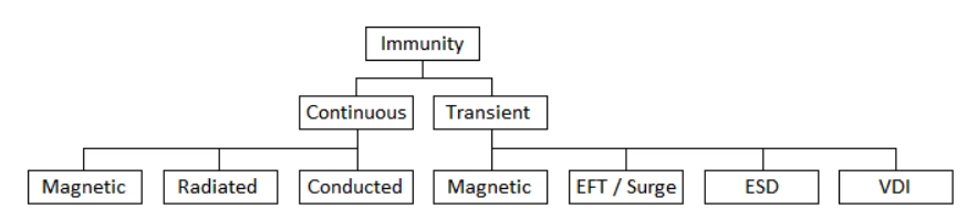
EMC immunity testing can be thought of as either continuous or transient in nature. Continuous testing is applied to a product to simulate RF proximity that may occur in the real world. Transient phenomena are typically short events that involve bursts of energy.
Continuous Immunity Testing
1. Radiated Immunity:
It is a test to assess the ability of an Equipment under Test (EUT) to withstand radio emissions from surrounding devices. It determines the radiated susceptibility threshold value of the device below which the device can operate safely. To elaborate, the test verifies if the EUT will operate as intended when subjected to a simulated RF noise level (equivalent to the actual operating environment), and evaluates the performance of the cables and internal circuitry of the EUT in an exposed electromagnetic environment. If the EUT operates as intended, then it passes the compliance test.
The IEC 61000-4-3 is an EMC standard by the International Electrotechnical Commission on the immunity requirements such as test procedures and test levels of electrical and electronic equipment to radiated electromagnetic energy. The tests are normally performed in the frequency ranges 800 MHz to 960 MHz and 1.4 GHz to 6 GHz. The frequencies or frequency bands to be selected for the test are only applicable where mobile radio telephones and other intentional RF emitting devices operate.
Along with the test equipment the standard has also specified the test levels. The test levels and the frequency bands are selected as per the electromagnetic radiation environment to which the EUT can be exposed when finally installed. The tests are normally performed in the frequency ranges 800 MHz to 960 MHz and 1.4 GHz to 6 GHz. The frequencies or frequency bands to be selected for the test are only applicable where mobile radio telephones and other intentional RF emitting devices operate. Following is the classification of test levels specified in the standard:
- Class 1: Low-level electromagnetic radiation environment: Applicable to local radio/television stations located at more than 1 km, and transmitters/receivers of low power.
- Class 2: Moderate electromagnetic radiation environment: Applicable to low-power portable transceivers (typically less than 1 W rating) which are in use, but with restrictions on use close to the equipment. A typical commercial environment.
- Class 3: Severe electromagnetic radiation environment. Applicable to portable transceivers (2 W rating or more) are in use relatively close to the equipment but not less than 1 m. High-power broadcast transmitters are close to the equipment and ISM equipment may be located close by. A typical industrial environment.
- Class 4: Portable transceivers are in use within less than 1 m of the equipment. Other sources of significant interference may be within 1 m of the equipment.
- Class X: X is an open level that might be negotiated and specified in the product standard or equipment specification.
2. Conducted Immunity:
During conducted immunity testing, an electromagnetic field is generated by an RF signal generator and amplifier. This electromagnetic field is coupled to a products signal, data or power port via an injection device (commonly a CDN, or ‘Coupling/Decoupling Network’ is used as an injection device). This kind of conducted immunity testing is continuous in nature and is called “Radio-frequency Continuous Conducted” in many standards. Typically conducted immunity testing is applicable to AC & DC ports and signal cables longer than 3m in length.
The IEC 61000-4-6 by the International Electrotechnical Commission is the RMC standard for induced disturbances caused by electromagnetic fields coming from intentional radio frequency (RF) transmitters in the frequency range of 150 kHz to 80 MHz. The test levels of the unmodulated disturbing signal (Vrms) are shown in the table below:
| Frequency from 150 kHz to 80 MHz | ||
| Voltage Level (emf) | Voltage Level (emf) | |
| U0 (V) | U0 (dB (µV)) | |
| 1 | 1 | 120 |
| 2 | 3 | 129.5 |
| 3 | 10 | 140 |
| X | Special | Special |
The “X” level is for the special cases, which can be above, below, or between any levels. It has to be specified in the equipment specification.
3. Power-frequency Magnetic Field Immunity:
A fluctuating magnetic field is produced by a magnetic coil that oscillates at the mains power frequency (50/60Hz). The EUT is placed inside this fluctuating magnetic field and exposed for enough time to evaluate the performance of the product. Magnetic Field Immunity Testing is usually only required for Magnetically Susceptible Devices.
Transient Immunity Testing
1. Electro-static Discharge (ESD):
ESD testing is conducted to check the quality of the operation of an Equipment Under Test (EUT) when subjected to an electrostatic discharge. This testing is used to check the performance of the EUT for personnel static charges as well as indirect charges i.e. static charge from personnel to EUT through some other object in its proximity. Personnel handling the devices carry static charges of some amount which is capable to damage most types of semiconductors.
Static charges can have a magnitude high enough to fire up sensitive circuits causing to malfunction or even damage to the system. Hence a device with proper ESD shielding is always more reliable for accurate results.
The IEC 61000-4-2 is used for ESD Immunity testing. It is an electromagnetic standard that specifies the limits, requirements, and test methods for electrical and electronic equipment subjected to static electricity discharges, from operators directly, and from personnel to adjacent objects. All people carry static electromagnetic discharge that gives rise to transient currents and electromagnetic fields that can interfere with electrical and electronic equipment. Hence, this standard for established to ensure that the equipment will work reliably and efficiently despite the static interferences in their work environment.
The standard has defined four levels of ESD protection, using two different testing methods.
| Contact Discharge | Air Discharge | ||
| Level | Test Voltage (kV) | Level | Test Voltage (kV) |
| 1 | 2 | 1 | 2 |
| 2 | 4 | 2 | 4 |
| 3 | 6 | 3 | 6 |
| 4 | 8 | 4 | 15 |
2. Electrical Fast Transient (EFT) / Burst:
Fast transients are a series of short pulses that are high in amplitude and repetition frequency with a short rise time. Fast transient phenomena are most often caused by high speed switching events such as interruption of inductive loads and relay contact bounce etc. Typically fast transients testing is applicable to AC & DC ports and signal cables longer than 3m in length.
EFT testing is conducted by subjecting Equipment Under Test to a series of fast rise time and duration pulses (5ns by 50ns respectively) to ensure compliance and meet product reliability requirements. The bursts or EFTs are generated by a burst generator that is connected to the EUT coupled onto power lines using a coupling-decoupling network (CDN). Along with power lines, EFTs testing is also conducted on communication, data, and signal lines.
The IEC 61000-4-4 is an EMC standard by the International Electrotechnical Commission for the immunity requirements of electrical and electronic equipment to repetitive electrical fast transients. This standard specifies the limits, requirements, and procedures to evaluate the performance of the Equipment Under Test (EUT) when exposed to repetitive fast transients (bursts) on supply, signal, and control ports. These transient bursts are the disturbances created by switching power currents, the opening of circuit contacts leading to sparks, and the switching of loads in a circuit.
The standard also classifies the test levels for EFT/B testing according to the requirements of the electromagnetic environment. These levels are:
- Level 1: Well-protected Environment e.g., a computer room.
- Level 2: Protected Environment e.g., a control room of an industrial plant.
- Level 3: Typical industrial Environment e.g., a relay room of open-air, high voltage power plant or substation of manufacturing plant.
- Level 4: Severe Industrial Environment e.g., substation switchyards.
3. Surges:
Surges are a type of transient phenomena produced by high powered switching events, magnetic/inductive coupling and even lightning. Surge testing on the mains port of a EUT is applied at several phase angles of the mains supply. Typically surge testing is applicable to AC ports and sometimes also DC ports and in some EMC product standards signal cables longer than 30m in length or if the cable may run outside of a building.
The IEC 61000-4-5 is an EMC standard by the International Electrotechnical Commission on surge immunity. It specifies the tests, methods, and recommended limits for equipment to unidirectional surges caused by overvoltages from switching and lightning events. The IEC 61000-4-5 focuses on immunity tests and procedures for power transmission and telecommunication lines.
IEC 61000-4-5 specifies several levels of tests in association with an environment. The standard has classified the operating environments for which the equipment has been designed. They are as follows:
- Class 1: Partly protected electrical environment.
- Class 2: Electrical environment where the cables are well-separated, even at short runs.
- Class 3: Electrical environment where cables run in parallel.
- Class 4: Electrical environment where the interconnections are run as outdoor cables along with power cables, and the cables are used for both electronic and electric circuits.
- Class X: Special conditions specified in the product specification.
The following table summarizes the surge voltages for different classes:
| Class | Test Voltage (±10% kV) |
| 1 | 0.5 |
| 2 | 1 |
| 3 | 2 |
| 4 | 4 |
| X | Special |
4. Voltage Dips, Short Interruptions (VDI) and Voltage Variations:
The purpose of voltage dips and short interruption testing is to simulate faults in the power network. These faults may be caused by power-cuts (blackout/brownout events) or by sudden large changes of loads. Voltage variations are typically caused by continuously varying loads connected to the power network. A voltage dip or interruption is a two-dimensional phenomenon that is characterised by the residual voltage (mains voltage after the specified dip) and duration (how long the dip in nominal voltage is applied to the product). This test is only applicable to AC input ports of products.
The IEC 61000-4-11 is an EMC standard by the International Electrotechnical Commission for testing and measurement techniques for voltage dips, short interruptions, and voltage variations. This standard specifies the tests, procedures, and limits for voltage dips, dropouts interruptions, and variations of electrical and electronic equipment working on an AC supply having a rated input current not exceeding 16 A per phase with 50 to 60 Hz.
Voltage dips and interruptions are sudden reductions of the supply voltage. These sudden reductions can affect the operation of the equipment. These dips are caused by load switching, faults in the main supply, etc. Voltage dropouts are dips that are 95 to 100% deep and may last up to 1 minute. If these voltage dips and dropouts occur in high-resolution imaging systems used for medical purposes such as MRI scans and CT scans even for one minute, then the systems would lose critical data over that period thus affecting their efficiency and reliability. Similarly, a momentary voltage drop in an amplifier or a receiver can cause transient glitches (noise) which could affect the load it is driving.
IEC 61000-4-11 specifies the test environment and test procedures also. Some of them are:
- The type designation of the Equipment under test (EUT).
- Information on possible connections, corresponding cables, and connectors.
- Representative operational modes of the EUT for the test.
- Performance criteria are used and defined in the technical specifications.
- Operational modes of EUT
- Description of the test setup.


![[MIC] Officially issued QCVN 134:2024/BTTTT - National technical regulation on specific absorption levels for handheld and body-worn radio devices according to Circular 19/2024/TT-BTTTT of Ministry of Information and Communications](https://cdn0577.cdn4s.com/thumbs/qcvn-134_thumb_150.jpg)